
Instrument Impact Testing
MPM manufactures several impact test systems that can perform a wide variety of impact tests including:
Charpy impact testing (ASTM E23)
Miniature Charpy impact testing
Drop tower impact testing (ASTM E208, E436, and E 604)
Plastic impact testing (ASTM D256, D1709, D2582, D3763, D5420, D5628, D5941, and D5942)
Dynamic Tear (ASTM E604 and E436)
Beverage can impact testing
MPM Instrumented Data Acquisition (DAQ) System
Most of the test machines can be provided with strain gage or accelerometer instrumentation. Instrumented test systems enable measurement of the force applied to the test specimen during an impact event. Then, the instrumented test data can be used to calculate the energy absorbed by the test specimen. In addition, the crack initiation and arrest loads can be used in fracture mechanics models.
System Features
The MPM instrumented system is very accurate and versatile. Some important system features are listed below:
Up to 1,000,000 data points per test
Data acquisition time ranges from microseconds up to 100 milliseconds (longer acquisition times available)
User friendly software controls acquisition and data analysis
Optical encoder data can be read and stored automatically
Full system includes:
computer
high speed 12 bit acquisition board
strain gage amplifier
instrumented striker
flat panel monitor, optical mouse and keyboard
hardware/software manual
software
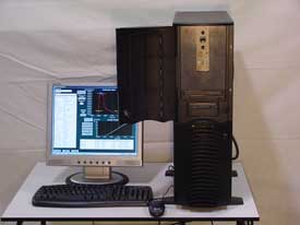
DAQ System Showing Strain Gage Signal Conditioner Inside Locked Case
Sample Instrumented Striker Data
The nature of the instrumented signal response depends on the material being tested (metal, plastic, ceramic, composite, etc.), the test temperature, and other key test parameters such as impact velocity. Shown below is a typical instrumented striker voltage response for a Charpy test on a metal test specimen at a test temperature in the transition region.
Instrumented Striker Voltage Response
The voltage-time curve is converted to a force-time curve through the load cell calibration. During the testing, the MPM system measures the impact velocity directly using an optical encoder (see Pendulum Machines page) or an infrared device (see Drop Tower page). This velocity is then used in the numerical integration of the measured force to determine the velocity-time curve. A second numerical integration is performed to obtain the displacement-time curve. These data are then used to construct the force-displacement curve, and the total energy absorbed by the test specimen is calculated by integration of this curve. These analysis steps are shown graphically below.
Integration Plots
Another analysis option is to determine characteristic loads, deflections, and energies. The general yield load (for metal specimens) is determined from the intersection of the elastic loading line and a fit of the data during load up. The peak load is determined by least squares regression of the data. Finally, for tests conducted in the transition region, the brittle fracture load and crack arrest load are determined from a robust data analysis algorithm. An example of the characteristic load report is given below.
Characteristic Load Report
System Upgrades
New test machines can be provided with an instrumented system or existing test machines can be upgraded by the addition of the MPM state-of-the-art system. MPM will assemble the system and provide a field installation and calibration if desired. The MPM system can provide all of your laboratory impact data acquisition needs since the system can be configured for pendulum machines and for drop towers.